Design and implementation of a hardware assisted security architecture for software integrity monitoring
Design and implementation of a hardware assisted security architecture for software integrity monitoring
In addition to the current’s actions of protecting system’s security, the author propose to design a new architecture that can perform integrity checks securely on any softwares that run on this architecture.
Current Issues:
With the fast developing of technology, systems are getting more and more complex. We all know that hardware platforms support the execution of multiple software components and nowadays, most of those hardware platforms have x86 processors and PCI Express bus as interconnections. Hardware platform is configured in the mainboard, BIOS (Basic Input/Output System), and after configuration, BIOS hands it over to either the kernel of the operating system or the virtual machines manager. All those components are pretty complex and hence, they are easy to be exploited and corrupted. Once the system is corrupted, the results are quite undesirable.
Although some security mechanisms have been designed to reduce the attacks, the approaches they take are far not sufficient enough. Most of those security mechanisms target to the integrity check at the boot time but they don’t check for integrity during runtime. Hence, the author proposes an architecture that can do constantly integrity check at runtime.

Assumptions of the design of the architecture:
- Assume attackers don’t have physical access to every component of the architecture
- Assume the attacks are performed through malicious software on the CPU
- Assume attackers are able to target both software and hardware components which means attackers can reconfigure hardware to use it at his convenience
Hardware Assisted Trusted Architecture:
The architecture is a hybrid mix up of software and hardware components. The approach the author takes is the black box approach solution. In this solution, the developers provide a set of integrity functions and the software component to execute. Those functions, so called integrity checks, are designed to check the integrity of the software component, so called guarded software.
The architecture is composed of two components: security hypervisor and trusted hardware component. While the hypervisor is a container of the set of the integrity checks and is running in the most privileged level of the processor, there is still possibilities of it being corrupted. Hence, we need an extra check of the integrity of this privileged component from an external processor that connects to the system but independent of its operating logic and behavior. Such an extra check leads to the second component of this architecture: the trusted hardware component. This component mainly responsible for checking the integrity of the hypervisor by checking both the correct behaviour and the correct configuration of the hypervisor. The trusted hardware component proposes challenges regularly to the hypervisor to execute and then collect and check the results of these challenges. in addition to that, it also designs a set of tests to detect any alteration of the code or any changes in the configuration of the hypervisor environment. If it detects any unusual activities or results, it raise alarm for that.

Hardware Infrastructure:
The architecture consists two x86 machines and a PCI Express peripheral. While the machines are the target machine and the trusted remote machine, the peripheral serves as the trusted hardware component.
The target machine executes the security hypervisor and the guarded software component. The machine is equipped with hardware virtualization assistance technology and also an Ethernet link. This Ethernet link is under the control of the hypervisor and is considered trusted as long as the hypervisor is not corrupted. The integrity check results of the guarded software component are also transmitted through this Ethernet link to the remote trusted machine.
The peripheral is composed of a ML605 Xilinx board and is plugged on the target machine with a PCI Express riser and an onboard PCI Express 8x connector. The peripheral (the trusted hardware component) is connected to a trusted local network to the trusted machine via its Ethernet interface.
The remote trusted machine runs on a COTS operating system where it not only collects the challenges results and integrity check results but also generate the challenges and transmit them to the trusted hardware component via a TFTP local server.
Integrity Checking Cycle:
There are three main phase of this cycle. Phase 1 is the test (challenges and environment checks) of the security hypervisor. Phase 2 is the performance of integrity checks on the guarded software component. Phase 3 is the waiting time between two occurrences.
Phase 1 is composed of two methods. In the first method, the trusted hardware component submits a randomly generated challenge to the hypervisor and the challenge is associate with an expected execution time. The response of this execution of challenge is collected and verified in the trusted hardware component. By associating an expected execution time, we can eliminate the possible malicious bypass made by attackers. the second method performs the environment checks on the security hypervisor. It also checks for the configuration of the environment. By doing so, it eliminates the possibilities of malicious alteration on the environment configuration which may not being detected by the challenges. Phase 3 is for checking the waiting times for the next cycle triggered by the trusted hardware component.
Trusted Hardware Component
This work is based on the adaptation of the Milkimyst project. The Milkimyst is an open source hardware and software System On Chip (SOC). With this design, a user can develop a high-level software intended to be executed directly within the FPGA. However, unneeded functionalities of the Milkimyst SOC have been removed to optimize the FPGA space. The implementation contains the following cores:
- a LatticeMico32 (LM32) micro-processor, 32 bits big endian Microprocessor;
- a Fast Automata Core, so-called hereafter FAC;
- an Onchip ROM;
- a PCI Express Endpoint implementation, so-called here-after PCIEE;
- an Ethernet MAC;
- a Configuration and Status Register bridge, the CSR bridge and a Fast Memory Link bridge to a DDR3 SDRAM controller, the FML bridge.

- Protocol phase1: challenge and environment checks
The architecture has been designed in order to challenge and check the integrity of the security hypervisor from the trusted hardware component.- Boot
Step 1: Boot (LM32): when the board is powered on, the LM32 executes a code within the ROM at an address configured during the SOC synthesis. This code is a basic firmware which configures low level components (the UART, the Ethernet MAC, etc.).
Step 2: Netboot (LM32, TM): once the board is basically initialized, the basic firmware executes a TFTP netboot loader to download a more complex firmware. This firmware configures remaining components of the board (uptime system timer, etc.). It also implements the challenges PCI Express service.- Challenge
Step 1: Challenge download (TM, LM32): the firmware downloads the next challenge via TFTP. This challenge is stored in memory of the LM32 for preprocessing. It must not be sent directly to the security hypervisor because it contains the solution.Step 2: Challenge preprocessing (LM32, PCIEE): the downloaded challenge is preprocessed (cf. section VI-B) in order to extract the solution (expected time and value). This memory is exposed as a PCI Expansion ROM which is mapped in the security hypervisor memory space through PCI Express.Step 3: Challenge notification (LM32, PCIEE, SH): the trusted hardware component sends an interruption to the CPU, notifying it that a new challenge is available. The security hypervisor has now a fixed delay of time to download and execute the challenge.Step 4: Waiting for challenge solution result (SH, PCIEE): the security hypervisor executes the challenge. At the end of this execution, the security hypervisor must write the solution within a dedicated memory of the hardware trusted component (PCI BARs). This event is tracked by the trusted hardware component using PCIEE events.Step 5: Solution check (LM32, PCIEE, Ethernet): the solution is written, by the security hypervisor, in the dedicated memory of the PCIEE.- Enviroment checks
Challenges are not the only way to check the integrity of the security hypervisor. The hardware trusted component is also able to check the integrity of the memory space of the security hypervisor or the integrity of the values of low-level structures (VMCS, page tables, hardware component configuration, etc.). These environment checks concern values that a malware must change in order to corrupt the security hypervisor.Step 1: Automata download (TM, LM32, FAC): the automata intended to be executed on the FAC is downloaded via TFTP.Step 2: Page download (LM32, PCIEE): the memory page to be checked is configured and a PCI Express DMA access is requested to the PCIEE.Step 3: Page Checks (LM32, PCIEE, FAC, Ethernet): once the page is downloaded, according to the type of the pageB. ChallengesA challenge is an algorithm which is composed of a set of atomic instructions whose execution times bounds are known. Every challenge algorithm compute a value called the solution from input data. Input data can be characteristic of the integrity of the security hypervisor (control registers, stack pointers or page entries) or not. They are used only once and randomly generated by the remote trusted machine. An important issue regarding the challenge design is the estimation of its expected execution time. To do so, the challenge is firstly executed offline on the same processor as the processor of the security hypervisor, with the timestamp counter, read before and after, to get its measured execution time (called rated execution time). We add to the computed time an extra arbitrary delay, to cover the PCI Express message propagation time and so obtain the expected execution time published with the challenge. Furthermore, the challenge is again executed offline, but virtualized with our security hypervisor, to get the virtualized rated execution time. The challenge must be designed in such a way that the virtualized rated execution time must be at least 3 or 4 time higher than the expected execution time. This difference allows our system to detect emulation or virtualization of our security hypervisor. To get such a difference, we choose specific instructions for the challenge, hard to emulate and / or which will produce unconditional VM Exits (cpuid, vmread, vmptrst). PCI Express physical bus and protocol stack may lead to flow variations due to an overload of the bus, that could invalidate the usage of an arbitrary extra delay in the computing of the expected execution time for a challenge. To face this, PCI Express specification proposes QoS mechanisms which enable to segregate PCI Express messages in traffic classes, ordering them by priority. By using the highest priority class for the messages exchanged by the trusted hardware component, we have additional guarantees that its messages are exchanged in a limited delay, even if the bus is overloaded by traffic class with lower priority. Finally, even if an attacker is able to perform DoS attacks at the physical level, generating artificial jitter after having gained the control on the transceivers of a vulnerable device for example, this attack will be detected by the trusted hardware component which will not receive the responses of the challenge within the expected delay. Finally, in the unlikely case where the natural jitter is too important, generating too much delay in the transmissions, it will result in an false positive alert. Let us note that in our experiments, we never encountered such a situation.Security HypervisorThe security hypervisor is designed to be as small and as simple as possible. To operate as the most privileged software component of the system, it needs to virtualize upper layers, correctly isolated with EPT. It also protects itself from attacks coming from malicious hardware, by controlling Port-mapped Input/Output (PIO) and Memory Mapped Input/Output MMIO spaces as well as configuring the IOMMU.- Installation and loading strategy
The security hypervisor is an UEFI runtime driver loaded in the preboot environment. The firmware loader prepares its code and data memory space and marks them as used for the operating system running above. Since the adopted strategy is to limit the code footprint of the hypervisor, after activating VMX operations and configuring the hypervisor, the control is immediately given back to the firmware in order to let it boot the machine as if the hypervisor were not present.- Runtime Protection
At runtime, the security hypervisor keeps control on the virtual machine thanks to the VM Exits generated by some privileged instruction execution attempts or by the set of instructions which unconditionally generate VM Exits like the cpuid instruction. Most of the time, their execution is allowed, except for modifications of VMX operations required configuration. The security hypervisor also forbids accesses to its memory space and the memory space of hardware components it wants to keep the hand on, like the Ethernet card used for remote control. Undesired accesses will result in VM Exits, called EPT violations. Also, DMA accesses from PCI Express devices are controlled with the DMA remapping capability of Intel VT-d’s IOMMU, protecting the security hypervisor memory space to be remotely modified. We note that the trusted hardware component accesses are allowed.Attack MitigationOur architecture is a security solution that can also be the target of attacks. This section shows how these attacks are mitigated. To the best of our knowledge, the attacks presented in this section are representative of the different strategies of well-known and documented attacks taken from the state of the art.- Full virtualization attack
An attacker could succeed to virtualize our security hypervisor, injecting malicious code in PCI peripheral expansion ROMs and being loaded at the next reboot. Virtualization or emulation of our hypervisor will be detected because the instructions used in the challenge are slower when virtualized or emulated.- Relocalization attack
An attacker may be able to exploit a hardware fault or a software vulnerability to relocate the security hypervisor in the memory and install a new hypervisor. The attack will be detected by challenges targetting special CPU internal structures or environment checks. For instance, the challenge can retrieve the location of the hypervisor within VMCS.- Direct Memory Access Attack
An attacker may be able to exploit vulnerabilities in PCI Express peripheral to DMA read and write into the security hypervisor memory space . Any malicious modification in the security hypervisor memory space will also be detected by the environment checks.- Security hypervisor Ethernet interface
An attacker may also be able to control the point to point Ethernet link (Ethernet 2) to the trusted machine. As a consequence, she may send malicious traffic or fake alerts through this Ethernet link. Challenges and environment checks performed by the trusted hardware component will detect this corruption.- PCI Express Interface
The trusted hardware component is physically connected to four PCI express lanes. It implements support for read / write in memory mapped registers and read only for its expansion ROM. These two spaces do not influence the behavior of the trusted hardware component internals. Attacker still may try to perform DoS attacks from the CPU or other components to influence the message propagation timing. These attempts will result in a detection by the trusted hardware component itself.- Trusted hardware component Ethernet interface
Trusted hardware component Ethernet interface is directly connected to the trusted machine through a dedicated point to point Ethernet link. As a consequence, we do not consider physical attacks on this link. Since the PCI Express interface to the CPU doesn’t provide any access to this Ethernet interface, attacks from the CPU are impossible.- Remote trusted machine threats
The remote trusted machine runs a classical GNU/Linux distribution and is supposed to include the same hardware/- software vulnerabilities and attack vectors of the same class of architectures. That is why this machine is totally isolated from every network during the runtime and why we do not consider attacks towards this trusted machine.ExperimentsThis section is dedicated to the presentation of validation experiments of our security architecture. In this section, some benchmarks experiments are described in order to evaluate the impact on system overall performances.- Hardware configuration
The target machine is a Dell precision T1700 with an Intel i7-4770 microprocessor and an Intel c226 chipset. It embeds 8 gigabytes of DDR3 SDRAM. The speed of PCI Express link to the trusted hardware component is 4x. The Ethernet interfaces of the trusted machine (Ethernet 2), trusted hardware component (Ethernet 1) and security hypervisor are connected to a gigabit D-Link DGS-1008D Ethernet switch. The trusted hardware component 8x PCI Express port is plugged in the mainboard thanks to a riser. An additional Ethernet interface of the target machine, used for network benchmarks, is a Broadcom NetXtreme BCM5722 and linked to a 100 megabit non trusted local network.- Benchmarks
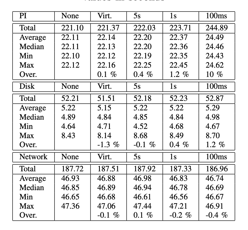
Three sets of benchmarks have been run on the architecture. Each set is executed on the target machine, firstly without our solution (None column in Table I) and with virtualization only. Then, the full solution is benchmarked, with guarded software integrity checks, environment checks and challenges, which are introduced in section IX-C. Finally the integrity checking cycle is executed every fixed period of time, for benchmarking purpose. Period is changed from 5s to 1s and 100ms. Every time a benchmark is executed, the target machine is rebooted to prevent boundary effects.The first set of experiments computes ten million PI decimals with GNU Multi Precision, for 10 iterations. The second set copies, by means of the dd Unix command, a 512 megabytes file, on the same disk, in a ext4 partition, 10 times in a row. The third set transfers over SSH a 512 megabytes file from the target machine hard disk to a remote machine in the non trusted local network, 4 times in a row.Looking at the results, for CPU burn-in test, measured overhead (table I) is less than 0.4 %, for a 5s period and less than 1.2 %, for a 1s period, which is very acceptable. The overhead is rising to 10 percents for a 100ms period because of the nature of the PI benchmark which only consumes CPU. This overhead can be drastically decreased (half of it at least) by optimizing the security hypervisor network communications (stopping the debug mode and context change communication) or optimizing the guarded software integrity checks. Let us note that a 100ms period is maybe too fast and won’t increase platform detection accuracy. This experiment is interesting but is not sufficient to estimate the performance of our architecture because a CPU burn-in experiment is not representative of the different use cases of a computer. This is why two other series of experiments are considered, focusing on disk and network usage. These experiments show that performance variations due to the disk accesses latencies and network communication delays are more impacting the system than our architecture. That is why negative and low overhead are measured, which shows that our solution provides very good performances.ConclusionIn this paper, we have presented the design and the implementation of a trusted security architecture that is aimed at securely executing integrity checks of any software running on top of this architecture. This architecture is composed of a security hypervisor, running in the most privileged mode of the processor, and an external autonomous hardware trusted component, independent of the processor, and checking the integrity of the security hypervisor itself. To face the problem that hardware solutions are not enough, we argue that a mixed software and hardware integrity checks execution architecture is more realistic because it enables to run software integrity checks inside a security hypervisor, while trusting this hypervisor thanks to environment checks and challenges realized from a trusted hardware component. Finally, several examples of attacks leading to the corruption of two guarded softwares have been successfully detected.


Comments
Post a Comment